ArUco cell
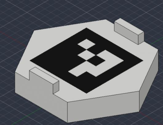
The ArUco cell provides a visual reference for locating HiveBoard in camera images. Its estimated pose can be used to place the board in a robot coordinate frame or align a simulated scene with a physical setup.
The cell is an optional accessory. Benchmark evaluations still contain 13 conditions with five trials each.
Files and materials
Download the files from CAD/ArUco Cell/.
| File | Purpose | Filament |
|---|---|---|
aruco_cell_base_white.obj | Hexagonal base and white marker regions | White PLA |
aruco_cell_marker_black.obj | Black marker insert | Black PLA |
aruco_cell_assembly.obj | Reference model showing both parts in position | — |
Keep each OBJ beside its matching MTL file. MTL files specify display colors. Select the filament separately in the slicer. Print the base and insert as separate parts.
Dimensions and import scale
The OBJ coordinates correspond to centimetres. Set the import units or scale explicitly.
| Quantity | Value |
|---|---|
| Overall width | 88.1 mm |
| Assembly bounding box | 88.1 × 76.297 × 22.0 mm |
| Nominal outer black square | 47.505 mm per side |
| Import into a millimetre-based application | Multiply coordinates by 10 |
| Import into a metre-based simulator | Multiply coordinates by 0.01 |
Apply the same scale to both parts. Confirm the assembled width before printing. For pose estimation, measure the printed marker from the outer edges of its black square. Use that measured side length in the detector.
Print and assemble
- Import the base and insert with the scale specified above.
- Print the base in white PLA and the insert in black PLA. Use the PLA printing settings as a starting point.
- Remove stringing and excess material from the mating surfaces.
- Fit the insert into the base, following the assembly model. Check that it is fully seated and the marker face is complete.
- For permanent assembly, apply a small amount of PLA-compatible adhesive to the mating surfaces. Keep adhesive off the marker face and allow it to cure.
- Seat the cell in the honeycomb base. Choose a position visible to the camera that leaves the required task cells available and the robot's approach clear.
Check that the cell remains fixed during manipulation. Recheck its pose relative to the board after moving or reseating it.
Marker and camera configuration
| Parameter | Setting |
|---|---|
| OpenCV dictionary | DICT_4X4_50 |
| Marker ID | 0 |
| Marker side length | Measured outer black-square side, in the units used for pose estimation |
The marker was created with chev.me/arucogen using 4×4 (50, 100, 250, 1000) and ID 0. This ID has the same pattern in the four standard OpenCV 4×4 dictionaries. Use DICT_4X4_50 for a consistent detector configuration.
Calibrate the camera at the resolution used for detection and retain its intrinsic parameters and distortion coefficients. Verify detection of ID 0 on the printed cell at the intended working distance and viewing angles. Check that the marker remains visible under the experiment's lighting conditions.
Pose estimation also requires the marker's position and orientation relative to the chosen board frame. To express the board pose in robot coordinates, obtain the camera pose in that coordinate frame. For a moving camera, use the camera pose corresponding to the image timestamp.
See the OpenCV ArUco documentation for detection and pose estimation.
Physical-to-simulation alignment
Import the assembly mesh with the correct scale and place it relative to the same board frame used in the physical setup. Use the measured marker-to-board transform when converting a detected marker pose into a board pose.
Check the resulting alignment at known points on the board before using it for robot motion or comparing trajectories. Record the coordinate-frame conventions, camera calibration, and marker-to-board transform. The cell provides a reference for geometric alignment. Physical parameter identification is described in Simulation assets.
Record with a dataset
When using the cell during DataHive collection, retain:
- the camera images and timestamps used for detection;
- camera intrinsics, distortion coefficients, and camera-to-robot calibration when used;
- the dictionary, marker ID, and measured marker side length;
- the marker-to-board transform and coordinate-frame definitions;
- any estimated poses, with their timestamps and detection failures.
Keep these calibration records with the session metadata. Agree on supplemental files with the organizers if they fall outside the current DataHive episode format. Installing DataHive does not configure marker detection or board-pose estimation.
For benchmark evaluations, record the localization method in the platform description and continue to record each trial with an external camera.